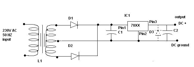
Circuit Diagram (Schematic Diagram)-1
L1 = Step down transformer with i/p of 230 AC 50 Hz and output of (XX ) - 0- (XX)) volts(rms).
XX = Required DC output voltage.
Here is the table for different voltages
| Output voltage (DC Volts) | Transformer rating (rms Volts) |
| 5 | 230: 5-0-5 |
| 9 | 230:9-0-9 |
| 12 | 230:12-0-12 |
| 15 | 230:15-0-15 |
The current rating has to be more than 1 Amp.
D1, D2 = Diodes 1N4003
D3 = Diode 1N4003/ 1N4001 (optional)
C1 = 1000 Micro Farad aluminum electrolytic capacitor (For loads less than 100mA you can sustitute with 220 microfards capacitor), Voltage rating = 2.5 times of Output Voltage.
C2 = 10 Micro Farad aluminum electrolytic capacitor
IC1 = 7805 for + 5V DC output
=7809 for +9V DC output
=7812 for +12V DC output
=7815 for +15V DC output
5V/9V/12V fixed power supply (Negative) at 1 Ampere current rating
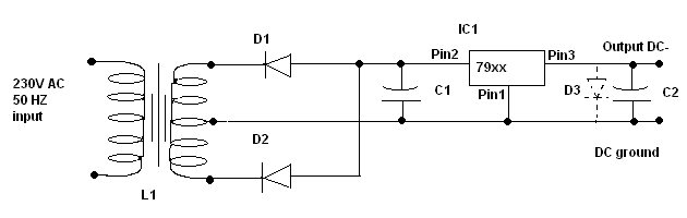
Circuit Diagram (Schematic Diagram)-2
L1 = Step down transformer with i/p of 230 AC 50 Hz and output of (XX ) - 0- (XX)) volts(rms).
XX = Required DC output voltages.
XX = Required DC output voltages.
| Output voltage (DC Volts) | Transformer rating (rms Volts) |
| 5 | 230: 5-0-5 |
| 9 | 230:9-0-9 |
| 12 | 230:12-0-12 |
| 15 | 230:15-0-15 |
D1, D2 = Diodes 1N4003
D3 = Diode 1N4003/ 1N4001 (optional)
C1 = 1000 Micro Farad aluminum electrolytic capacitor(For loads less than 100mA you can sustitute with 220 microfards capacitor). Voltage rating = 2.5 times of Output Voltage.
C2 = 10 Micro Farad aluminum electrolytic capacitor
IC1 = 7905 for -5V DC output
=7909 for -9V DC output
=7912 for -12V DC output
=7915 for -15V DC output
Additional note: It's safer to put one heat sink to 78XXX and 79XX IC for safeguarding the IC from overheating
In case you are using both the power supplies the ground connection of both positive and negative power supplies can be shorted.
No comments:
Post a Comment